Revision 2.9


Example of cluster with board connector problems
Revision 2.9
Example of cluster with board connector problems
Videos of this repair! Click Here
If you're considering doing this, you have a 25+ year old Corvette. Vibrations, current flow, heat and time conspire to cause internal components to break down and solder joints to break. This manifests itself in the following ways:
The four bulbs which illuminate the cluster remain dark, even with the ignition on
When the ignition is on, the cluster remains dark and the info can't be seen
Sometimes, hitting the dash or hitting a bump causes the cluster to start working properly
The four illumination bulbs light up, but they're really dim (or too bright)
Shining a flashlight on the cluster causes the information to appear
You can see the info on the cluster during the day, but not at night
The cruise control won't set
The colored info on the LCD panels appears, even when the cluster is off (they should appear black)
The LCD panels light up, but the information can't be read, except with polarized sunglasses or our free test sample (email us for your free sample).
The illumination bulbs are off, and segments on the LCD panels randomly flicker
Checking these things might save you a lot of work!
Check the fuses that support the cluster. These are marked "CLSTR", "TAIL", "INST" and "LCD".
Make sure the headlight dimmer switch is rotated completely to the bright setting (fully clockwise)
Turn the key on. For the first few seconds, the lamp test should cause all segments on the cluster to be on. Make a note of any that are not on during the lamp test.
Cover the photocell port (top left of cluster housing). The cluster should dim noticeably.
Set the DIC switch to Volts and make a note of the battery voltage. The testing procedures probably won't be conclusive if the battery voltage is less than 11.5V.
Check the factory wiring at the cluster harness. Click Here for more info.
25-40W Pencil Soldering Iron with pointed cone tip ($8.99 at Radio Shack - don't use soldering guns or higher heat soldering irons! If tip of the iron isn't clean, smooth and tinned, don't use it - you'll damage the circuit boards)
Rosin Core Electrical 60/40 Lead/Tin Solder. Don't use acid core solder or lead-free solder! We supply the correct solder with all of our components which require soldering.
Solder wick / Desoldering Braid from Radio Shack (or a desoldering method of your choice)
Replacement Board Connector repair kit - Click Here to buy.
Optional LCD polarizing filter kit - Click Here to buy.
Optional Photocell Kit - Click Here to buy.
Optional Xenon bulb kit - Click Here to buy
Optional Power Supply Rebuild Kit - Click Here to buy
Or optional New Power Supply - Click Here to buy
Windex and Cloth paper towels
Canned Air / Compressed Air
Isopropyl Alcohol and cotton swabs
Optional, but really good insurance: Static control wrist strap (Radio Shack)
Follow the removal instructions located here.
Seriously consider replacing the factory bulbs with cool-running Xenon bulbs, as the Halogen bulbs can destroy your cluster. Click Here to buy.

Examples of heat damage from factory bulbs
Sunlight causes the LCD polarizing filters to fade, which causes the information on the cluster to disappear. The LCD panels should appear black while the cluster is off. If you can see the colored info when the cluster is off, the polarizing film has faded and should be replaced. Click Here to buy.

Example of cluster with sun-faded polarizing film
If you're having issues with the cluster being too bright or too dim, consider replacing the photocell while the cluster is apart. Click Here to buy.

Example of cluster with defective photocell
Partially disassemble the cluster using the documentation here.
Complete the disassembly of the cluster using the documentation here.
Removing Solder: Use the solder wick to remove the solder which holds the old components in place. Place the wick over the solder to be removed and heat the top side of the wick. When it's hot enough, the solder will flow from the connection to the wick. Use a fresh (copper-colored) piece of wick for each removal.
When soldering, heat the connector lead and the solder pad on the circuit board (simultaneously). Once these two locations are sufficiently heated, feed fresh solder into the joint.
Over time, heat, vibration and bad design cause the board connectors or their solder joints to fail. Not all look as bad as the one in Figure 1, but they almost always need to be replaced.

Figure 1 - Burned Board Connector
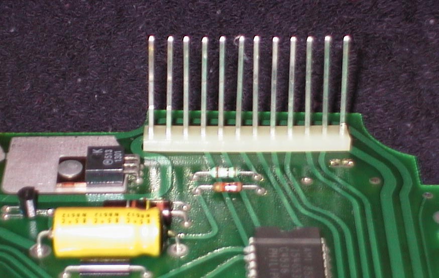
Figure 2 - Bottom of Board Connector Before Replacement
3) On the bottom circuit board (the one you took out last), remove the old connector using a soldering iron and desoldering braid or another desoldering method of your choice. When the solder has been removed and the connector is ready to be removed, you should be able to pull it away from the board by hand. Don't use force to remove the connector, as the hole plating (which connects top traces to bottom traces) can be damaged! See Figure 2.
 Figure 3 - The bottom board connector after removal - bottom of board
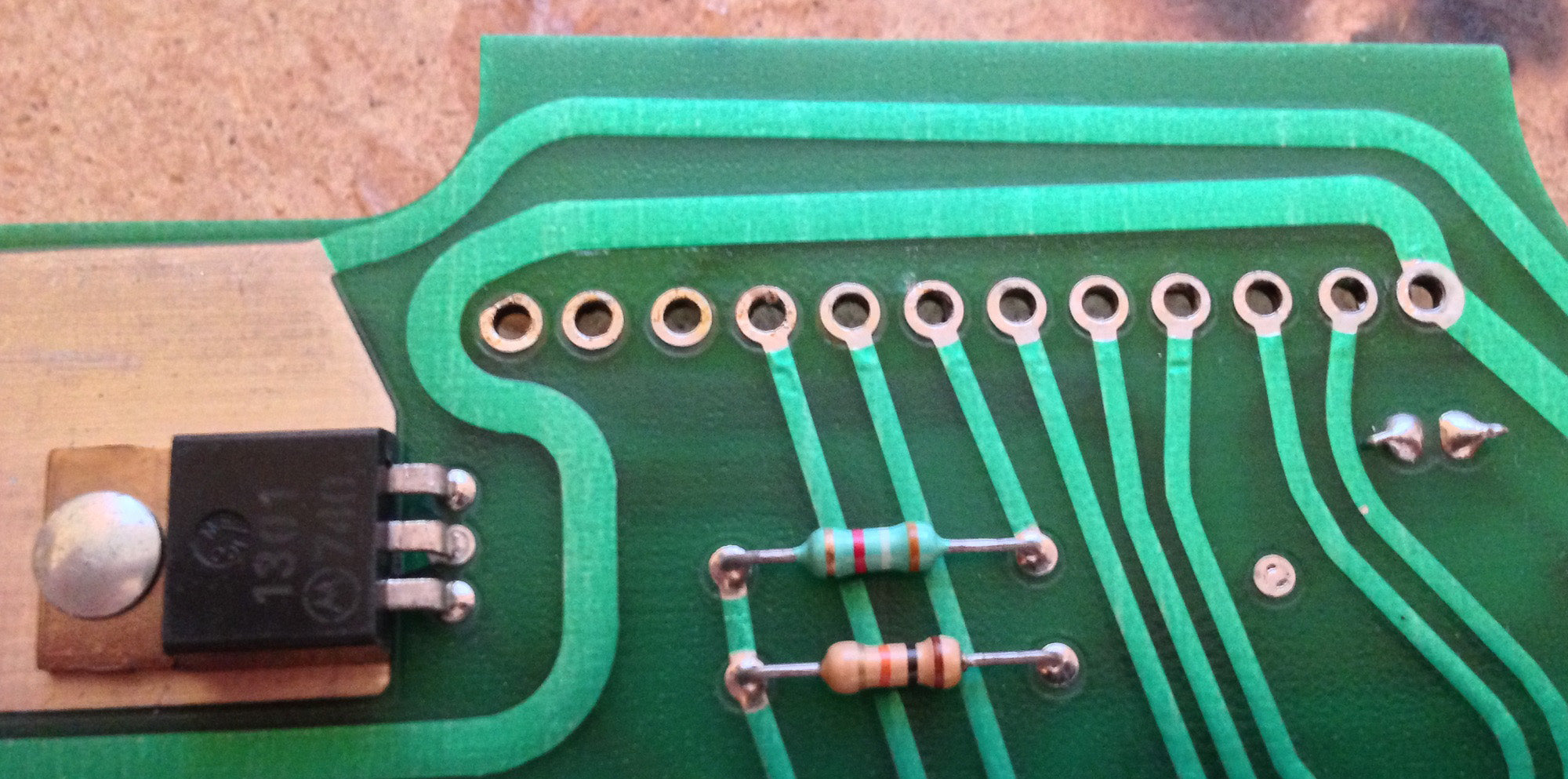 Figure 4 - The bottom board connector after removal - top of board
4) The connector will tend to warp when resoldered, which results in unevenly spaced pins. You can prevent this by temporarily installing the top board connector onto the pins of the bottom board connector.
5) Solder the pins of the new connector to the board.

Figure 6 - The bottom connector after installation - bottom of board
 Figure 7 - The bottom connector after installation - top of board
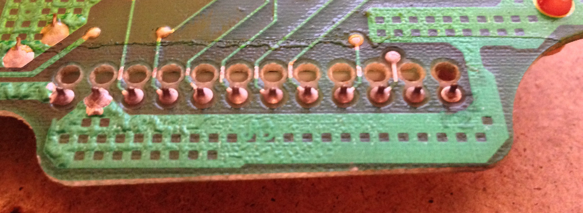 Figure 8 - The top board connector before replacement - bottom side of board
6) Using a soldering iron and desoldering braid (or a desoldering method of your choice), remove the old white connector from the top board. When the solder has been removed and the connector is ready to be removed, you should be able to pull it away from the board by hand. Don't use force to remove the connector, as the hole plating (which connects top traces to bottom traces) can be damaged!
 Figure 9 - The top board after removal - top side of board
 Figure 10 - Reinstalling the top board connector - bottom side of board
7) Next, resolder the new connector into place using 60/40 Tin/Lead Rosin Core solder.
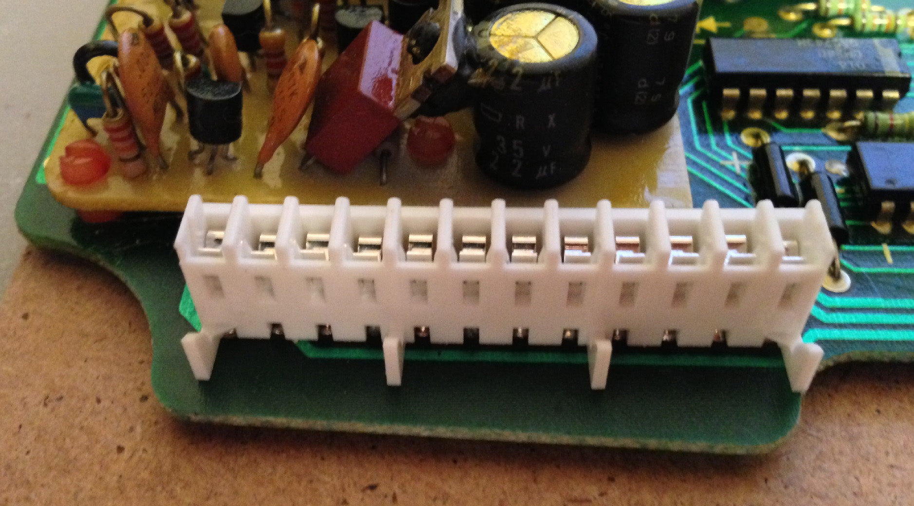 Figure 11 - Top Board Connector after installation
8) Using alcohol and cotton swabs, clean the excess rosin from the connections and board.
9) Desolder and then resolder the joints on the yellow board capacitor shown in Figure 7
10) Desolder and then resolder the brown resistor shown in Figure 7
11) Desolder and then resolder the dimmer transistor (the black thing with three leads) shown in figure 7
12) Heat from the factory bulbs causes the riveted connection of the dimmer transistor to become loose over time. Scrape the sides of the heat sink tab (opposite end from the three leads) and then solder it to the large heat sink pad on the bottom board. See Figure 7.
13) Inspect the polarizing filters on the LCD panels. If you see a fade ring around the edges, consider replacing the polarizing filters on the LCD panels. Now is the time to do that repair. Click Here to purchase.
 Figure 12 - Sun-faded film on left, new film on right
 Figure 13 - If you can see colored info when the panel is off, the polarizing film has faded
14) Follow the detailed instructions to install new polarizing film - Click Here
15) If the black paint on the back of the LCD panels has worn through, light will shine through the panel in areas other than the places it should. Use black enamel acrylic paint designed for glass and a small paint brush to repaint that area. Note that we supply the correct paint and a brush if you purchase our LCD Polarizing Film kit. Be careful to avoid areas near the factory graphics, and in the areas of the LCD segments!
Note: Let the paint dry completely before reassembling, or the panel will stick to the colored diffuser sheet!
17) Hold the painted panels up to the light to be sure the new paint completely blocks the light. Retouch if necessary.
If your cluster displays randomly flickering LCD segments along with intermittent backlighting, the onboard power supply (Fig 1) may need to be rebuilt. We sell a kit of parts to replace commonly needed components - Click Here
The documentation for troubleshooting and rebuilding the internal power supply is located Here.
If you'd rather replace the power supply than fix it, Click here
 Example of cluster with defective photocell
If your cluster is too dim during the day, or too bright in the evening or night, it may have a defective photocell. This is a low-cost part, and while the cluster is apart, it's a great time to replace the photocell.
While the cluster is powered on, hold your hand over the photocell (top left corner). The cluster should dim noticeably. If not, the photocell may be defective. Consider replacing it with parts available here
You can also use a digital multimeter to check the photocell. Measure the resistance of the photocell (while it's in-circuit is fine). It should measure <75k Ohms when exposed to room light, and > 1 Megaohm when dark. If it doesn't, the dimmer functionality won't work properly. Consider replacing it with parts available here
Follow this documentation to replace a defective photocell Click Here
Partially reassemble the cluster using the documentation located here.
Complete the reassembly using the documentation located here.
Consider bench testing the cluster - Click Here
Turn off the ignition before reconnecting the cluster!
Reconnect the instrument panel to the two electrical connectors and turn the ignition on.
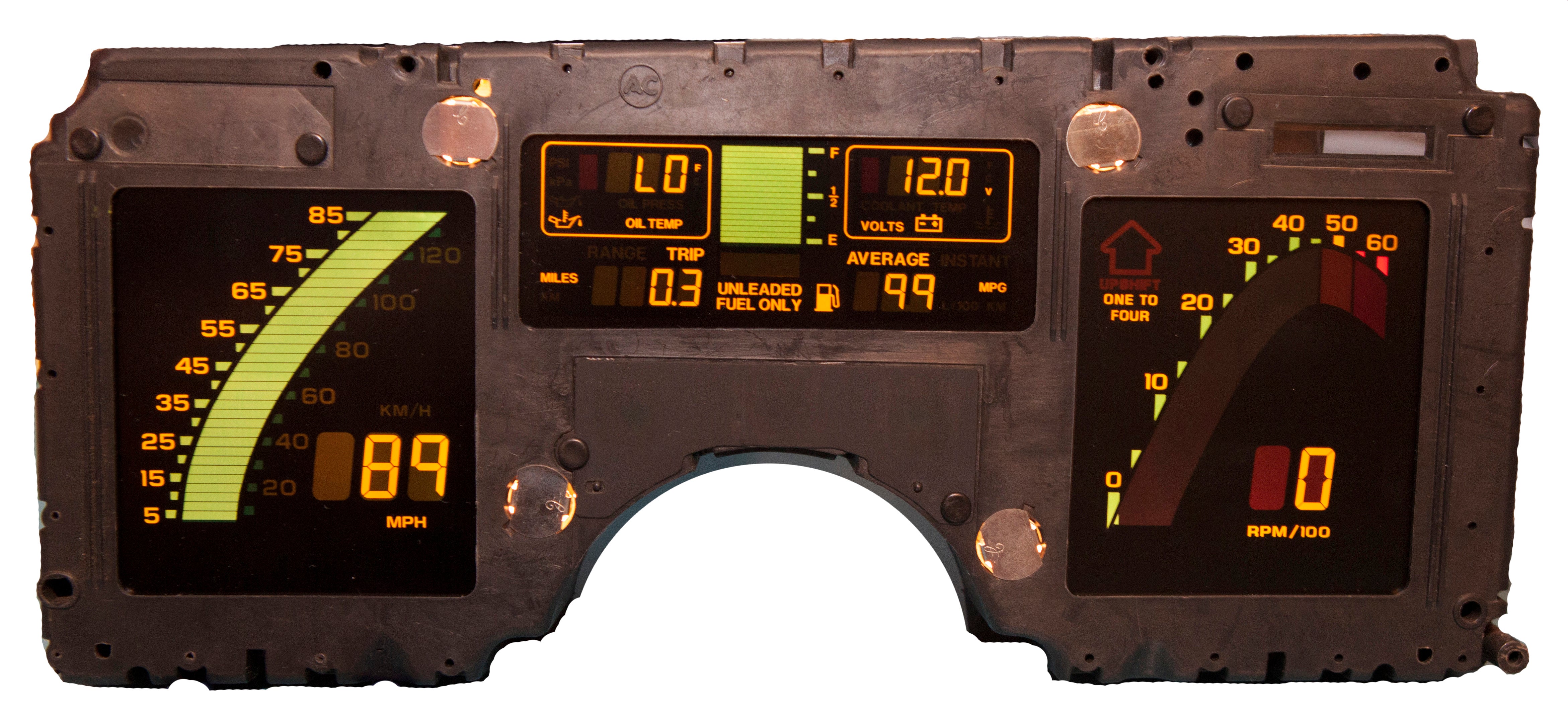
Figure 14 - Cluster after repair