90-96 Corvette Cluster Replace LCD Connector

This is the most common repair needed for the 90-96 Digital Cluster!
It takes some time to remove the gauge cluster, so why not replace all the bulbs while it's apart?
Click Here to buy a complete set of Bulbs and Bases
LCD Connector Replacement Instructions
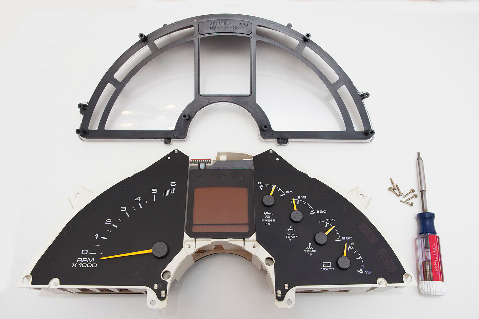
Supplies you'll need for this project
Replacement LCD Connector Kit - Click Here to buy.
Optional Replacement Polarizing Film Kit - Click Here to buy.
Optional Bulb Kit - Click Here to buy.
7/32" nutdriver or Torx 15 screwdriver
Soldering Iron (15-25W)
Some method of removing solder, such as desoldering braid
Click Here for a Video of the Repair Process
Disassembly
Using a 7/32" nutdriver or T15 Torx bit, remove the six screws holding the protective cover (circled in red in the images below):


Remove the protective cover and set it aside.

Carefully lift the top of the LCD until the pins release from the socket. Then slide it up and away from the plastic tabs holding the bottom of the display.

Remove the rubber gasket and translucent color filter.
Turn the white plastic housing over and separate the motherboard from the plastic housing.

Replacing the LCD Connector
The board connector is shown in the photo below. In this case, the problem is easy to see - a wire has broken. In the majority of clusters, the contacts of the cluster wear, then oxidize and pit. The oxidation is non-conductive, which is why the LCD eventually stops working. In other cases, the contact spring terminals weaken to the point that they no longer make reliable contact with the LCD pins. In all cases, replacing the connector is the solution.

The board connector solder joints are circled in red in the image below:

Using desoldering braid or a method of your choice, remove the connector wiring harness connector from the PC board and remove the LCD connector.
One side of the connector has ten metal terminals showing. Make sure to orient the new connector such that those metal terminals are facing the top edge of the motherboard. Solder the new connector in place, making sure that the wires do not cross. The leftmost wire on the connector should connect to the leftmost hole in the board, the next wire on the connector should connect to the next hole in the board, and so on. See the photo below.

Polarizing Film Replacement
Click Here for instructions on replacing the polarizing film:
Click Here
Reassembly
Press the logic board onto the needle movement pins protruding from the white plastic housing.

Assemble the LCD panel, rubber gasket and color filter as shown in the image above. If you're replacing the LCD panel, be sure to use the new panel.

Carefully slide the bottom of the LCD into the plastic housing.
Line up the pins of the display with the holes in the socket.

Slowly press the LCD into place, making sure that the top right corner clears the plastic tab shown in red in the image above.

Replace the protective housing and install the 6 screws removed in step 1.

This completes the repair process.
