90-96 Corvette C68 ECC HVAC Repair

The 90-96 C68 HVAC Controller Module

The 90-96 C68 HVAC Programmer Module
Over time, heat can cause the capacitors in your C68 Control Module and Programmer module to dry out and eventually short. Protection diodes and communications transistors can be damaged by reverse or 24V jump starts. Age and pot holes cause the bulbs in the control unit to blow. Solder joints on the solenoids turn cold and solenoids stop working. This restoration kit addresses all of these problems.
Symptoms
-
The control unit display is blank, or the display shows "---"
-
The control unit operation is intermittent or locked up
-
The control unit functions, but the buttons and/or display don't change mode
-
The control unit buttons and/or text are not illuminated when they should be (night / headlights on)
-
Cold air blows from the vents when heat is selected, or hot air blows when AC is selected
-
One or more solenoids doesn't work
-
One or more buttons or lights on the controller don't work
Kit Contents
1 - Large Capacitor for programmer
4 - Small Capacitors marked 22uF for programmer and controller
3 - Small Capacitors marked 39uF for programmer and controller
5 - Bulbs for Controller
5 - Surface Mount Communications Transistors for programmer
2 - large diodes for controller and programmer
2 - small diodes for controller and programmer
1 - Batee.com 3D Printed Controller Spacer Plate
1 - filter foam
1 - nut and washer to reattach vacuum lines to programmer
1 - Supply of solder
Supplies you'll need for this project
-
90-96 C68 ECC HVAC Restoration Kit - Click Here to buy.
-
3/16" nutdriver or socket
-
1/4" nutdriver or socket
-
Wire Cutters
-
A 15-25W soldering iron
-
Desoldering braid or a solder remover of your choice
-
Tweezers
-
Xacto knife
-
Sharpie or other marker
-
Windex / Glass Cleaner
-
91% Isporopyl Alcohol
-
Some sort of brush (an old toothbrush will work)
-
Optional can of compressed air
-
Optional DeOxIt contact cleaner
-
Paper Towels
-
Black electrical tape or masking tape
Removal Videos
Repair Video
Repairing the Controller
1) Remove the six 3/16" screws in the back side of the controller and set them aside. Note: One on the back may be located under a foam cushion. These are shown circled in red in the photos below.

Location of 3/16" screws holding plastic case on

More 3/16" screws
2) Pull on the faceplate to remove the faceplate and logic board from the plastic housing.

Case Removed
3) Detach the LCD connector at the location where it connects to the main logic board.

LCD Connector Disconnected
4) Pull the faceplate away from the main logic board and set it aside.

Faceplate Removed from main logic board
Reflector and Bulb removed from main logic board
5) Locate the single electrolytic capacitor on the main logid board. Note the side with the white stripe, and make a mark on the logic board on the board on the side of the white stripe. This indicates where the negative terminal of the new capacitor should go.

The Cap to be replaced is circled in Yellow
6) Install the new capacitor and solder it in place.
7) Remove the four grey bulb from the faceplate and one grey bulb from the main logic board and replace them with the bulbs provided in the kit.

Remove the faceplate bulbs circled in blue
11) Remove the two 3/16" screws from the back side of the faceplate. These are shown circled in red in the image below.

Remove the two 3/16" screws circled in red
12) Gently lift the circuit board away from the plastic switch contacts.
13) Remove the grey rubber switch contact sheet and set the button assembly aside.

Remove the faceplate circuit board and grey rubber switch contact sheet
14) Using alcohol and a paper towel, clean the black pads on the back side of the switch contact sheet. Use canned air or allow to air dry before reassembling.
15) Apply black tape or masking tape so that the ends of the pins are covered. Resolder the solder joints where the faceplate pins protrude from the faceplate circuit board. Do this as close to the circuit board as possible, making sure to keep solder off the ends of the pins (the part that connects to the main logic board). Do this for both sides of the circuit board. Using alcohol and the brush, clean any flux left behind from the soldering process. Two or three soakings of alcohol and two or three brushings should be enough. Clean the pins with alcohol and a paper towel to remove any adhesive residue and flux residue. Clean the black squiggle switch contacts on the front of the faceplate circuit board with alcohol and a paper towel, and allow to dry completely before reassembling.

Faceplate connector solder joints are circled in yellow

Make sure to solder each pin on both sides of the circuit board
16) Place the faceplate button sheet with the black dots facing away from the plastic buttons as shown. Make sure the indexing pins are aligned with the holes in the rubber sheet. Place the circuit board over the rubber sheet, making sure the indexing pins protrude through both rubber sheet and the circuit board, then reinstall the two black 3/16" screws which hold the circuit board to the faceplate plastic. Reinstall the four bulb housings in the faceplate.

The indexing pins for the rubber sheet and circuit board are shown in green

Here the faceplate circuit board has been installed
17) Reinstall the long bulb holder in the main logic board. Replace the white reflector assembly. Optionally spray the faceplate connectors, the wiring harness connector, and the LCD connector with DeOxit and allow to dry before reassembly.
18) Reattach the faceplate to the logic board, making sure that all of the pins fit into a hole in the main logic board electrical connector, and that there are no pins on either end of the connector which haven't gone through the mating connector. Press the faceplate completely onto the connector until the faceplate circuit board touches the main logic board. Reattach the white LCD cable to the main logic board.

Align pins with holes in main board connector

Align LCD Connector and Connect it to the Logic Board
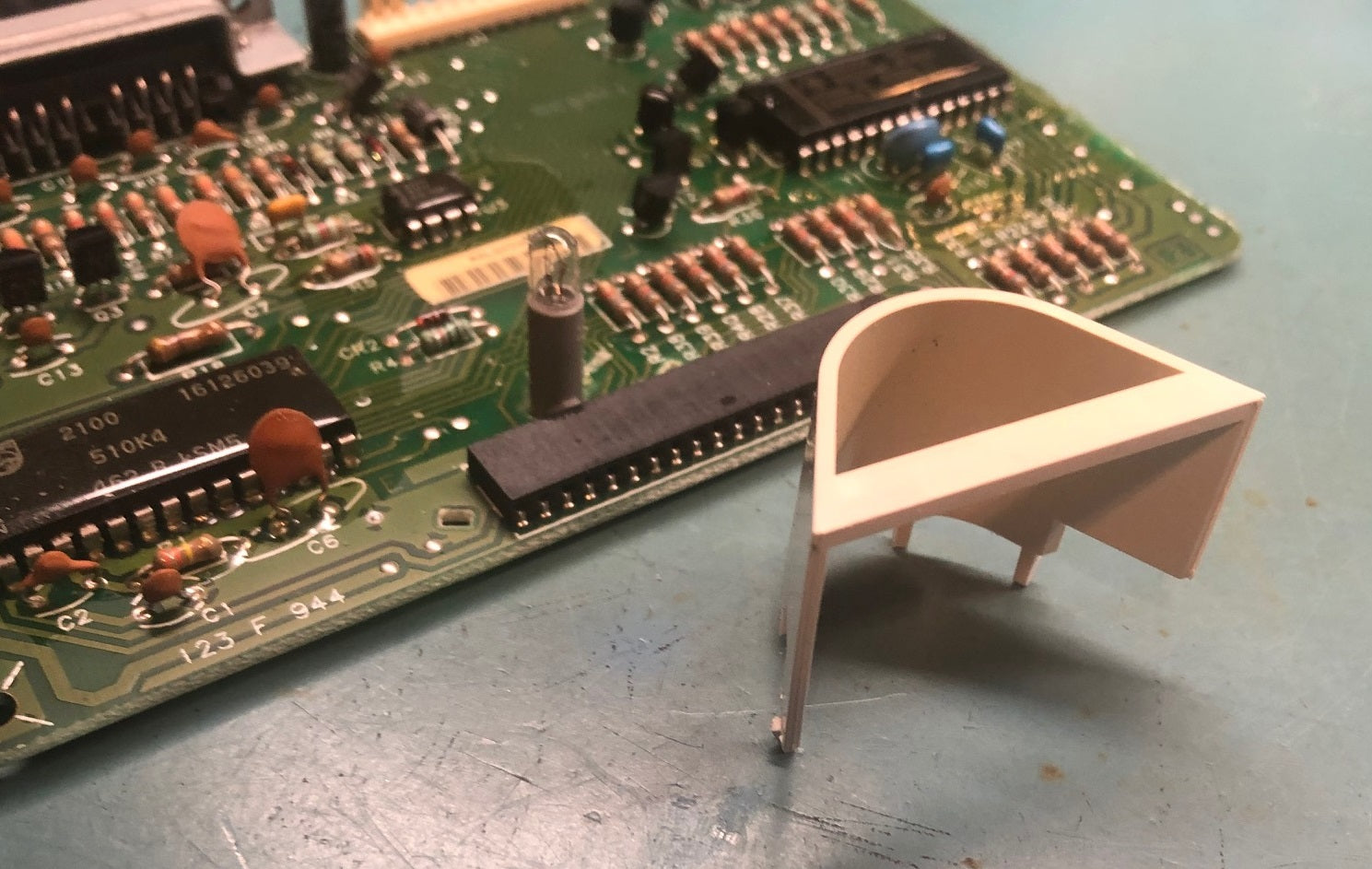
19) Place the 3D printed spacer onto the wiring harness connector of the main logic board. The holes in the plate should line up with the holes in the wiring harness connector. Replace the plastic housing, and install the four longer silver screws which hold the plastic case onto the faceplate.

Spacer plate installed on wiring harness connector
20) Replace the two short silver screws which steady the wiring harness connector to the plastic housing.

Spacer plate and wiring harness connector screws installed
This completes the HVAC Controller Repair Process. Continue on to the programmer repair.
Repairing the Programmer
Note: We are frequently asked if it's necessary to rebuild the programmer module. It's significantly more difficult to remove than the controller. The answer is, "Yes!" We estimate that 90+% of the problems with HVAC, especially the intermittent, blank or "---" display, and lockups are caused by the programmer module. The programmer is the computer for the system, and acts as the power supply for all components. If the LCD display is intermittent or blank, or displaying "---", rebuild the programmer!
21) Cut the tape holding the cardboard cover on the back of the programmer.
22) Remove the two 1/4" screws holding the vacuum solenoid board to the plastic housing. These are shown circled in blue in the images below.

Remove the 1/4" screws circled in blue
23) Disconnect the electrical connector on the vacuum solenoid board and remove the vacuum hoses as one assembly from the solenoids by pulling the clear plastic tube away from the four solenoids with your fingers. The vacuum lines are not glued to the solenoids and should pull away easily. Set the solenoid board aside.
 Remove the vac lines and electrical connector as shown

Remove the vacuum solenoid board
24) Remove the two 1/4" black screws holding the programmer logic board to the plastic housing, and then remove the board from the housing. These are shown circled in blue in the image below.

Remove the two 1/4" screws holding the programmer logic board shown circled in blue

The boards have been removed from the plastic housing
25) Make a mark on the programmer logic board on the side of each of the four aluminum cylinder capacitors, on the side of the white stripe. This is where the negative terminal (white stripe) of the new capacitor will go.
26) Note: There are two different styles of circuit boards. Use the image below which looks like your board as a reference. Remove the old capacitors one at a time. Using the desoldering technique of your choice, remove the old solder from the capacitor holes on the programmer logic board. Look at the value on the capacitor, and replace the capacitor with one of that value from the kit. 100uF capacitors are circled in red in the images below. 22uF capacitors are circled in yellow in the image below. 39uF capacitors are circled in blue in the images below. Make sure to install it with the white stripe toward the mark you made on the board, then solder the capacitor in place. Repeat for each of the other three capacitors.

Programmer Logic Board Front Side - Old Style

Programmer Logic Board Front Side - New Style
27) Note: Only do this step if your controller had a blank display when it should have been on, or when the display reads "---". If you don't feel comfortable making this repair, feel free to send it in to us. We only charge 1/2hr shop labor ($50 as of this writing, plus a few bucks return shipping) to replace the transistors, or $100.00 to completely rebuild the programmer (using the kit you purchased), and we'll completely test it. Turn the board over and locate the four or five black transistors shown circled in purple and sometimes in orange in the image below. These are the small devices which have three terminals (other devices only have two terminals). Unsolder them all using the technique of your choice and set them aside. Remove any additional solder from the three pads. Using the tweezers, hold a transistor above the pads, making sure that one leg is over each of the three pads, and solder one leg in place. Next, press down on the transistor with the tweezers and solder the other two legs of the transistor. Repeat for each of the other three or four transistors.
Note: If your board is the old style, there may or may not be a transistor in the location circled in Orange. If it's there, replace it. If not, don't install one here.

Programmer Logic Board Back Side - Old Style

Programmer Logic Board Back Side - New Style
28) Check the wiring harness connector and clean with a wire brush and DeOxIt contact cleaner if you see any green/white corrosion. If your connector has any broken or discolored pins, contact us for a replacement connector.
29) Look at the solder joints which mount the vacuum solenoids to the vacuum solenoid circuit board. If they look shiny and silver, leave them alone. If you see any separation of the solder from the pin, or if you see anything that looks grey or crystalline, resolder those solder joints.
30) Look at the foam / cork on the back of the solenoids. If it is crumbling, consider replacing it with the black foam in the kit.

Old Foam / Cork / Sponge material still installed
31) Lift up on the metal keepers holding that foam in place and remove them from the solenoids.

Old material removed
32) Using scissors or the Xacto knife, cut a strip of foam the height of the solenoid faces

Lay the strip of foam along the solenoid faces

Cut a strip of foam the height of the solenoid faces
33) From that strip, cut four squares of foam the width of a solenoid.

Cut four pieces of foam the width of the face of the solenoid
33) Using an old plastic card cut to the width of the solenoids, compress the foam.

Compress the foam using an old plastic card cut to the width of the face of the solenoid
34) Slide the metal keeper over the solenoid and foam, and then slide the card upward slowly to release the foam. If the foam bunches up, just remove the keeper and try it again.

Slide the metal keeper over the compressed foam and the end of the solenoid

New foam, card and keeper in place

Slide the card up slowly

Slide the card up slowly
New foam installed
35) Clean the plastic housing if needed.
36) Install the programmer logic board in the plastic housing. Replace the two 1/4" screws which hold the board to the plastic housing.
37) Reconnect the connector from the programmer logic board to the solenoid board. Replace the vacuum solenoid board in the plastic housing and replace the two 1/4" screws which hold it to the plastic housing. Reconnect the vacuum lines and electrical connector as shown below.

Vacuum lines and electrical connector reconnected, 1/4" screws reinstalled
38) Using black tape, tape the cardboard to the plastic housing.
This completes the repair process for the HVAC Programmer Module
Where do the diodes go? These aren't a part of the typical repairs to the controller or programmer, but sometimes a diode can be damaged by a reverse jump start or 24V jump start. If you see any diodes which have blown up (cracked in half, smoked, smell of fried electronics), go ahead and replace them with ones from the kit.
Tip We recommend temporarily connecting both components and powering up the system with the key on and engine running, and completely testing the system before you reinstall the components permanently.